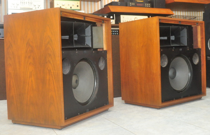
 I acquired a pair of 604Bs in the early 1990s, and had them refurbished with new 604E low frequency (LF) cones and new 16 ohm high frequency (HF) diaphragms at the Altec factory in Oklahoma City, Oklahoma. I subsequently used them with Altec N1500A crossovers for years in a secondary audio-visual system. (Follow the Vintage Altec Lansing N1500A schematic link for a look at that vintage series type crossover) My main system had horn loaded Altec 515-8Gs and 909-8As with custom phase corrected passive crossovers, and the 604Bs seemed to lag behind them in a number of sonic areas. In 2003 I started pursuing a crossover upgrade for the 604Bs so they would more closely match my main system. One important goal of this upgrade would be to correct for the phase shift between acoustic centers of the duplex design.
Phase Shift Between Drivers
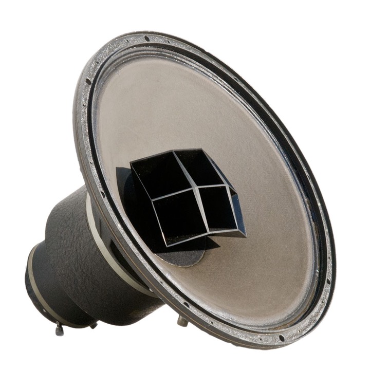
One of my concerns in getting a 604 crossover “right” was compensating for the phase shift between the acoustic centers of the LF and HF sections in the crossover region. Altec duplex drivers have a horizontal separation between their voice coil centers; alnico motor 604s have 5.375 inches, 605A/Bs have 4.25 inches and ceramic Altecs are 2.8125 inches. As a result, at 1500Hz the phase shift between the sections for these three would be 215, 169 and 112 degrees respectively. It’s obvious that whichever duplex type is used, its filter needs to account for this phase shift to ensure reasonably flat SPL magnitude throughout the crossover region.
Crossover Frequency and Filter Order
Another concern was the frequency of the crossover itself and the steepness of its slope. It was desirable to have a frequency and filter order high enough to ensure adequate crossover region horn loading and driver protection for the HF section, but this needed to be traded off against the rapidly rising impedance and falling non-pistonic SPL output of the LF section as frequency increased. Depending on the 604 horn used, and the steepness of the crossover slope, there is a limited range of frequencies to choose from. And, once you choose a crossover frequency, you have determined the actual phase shift between the LF and HF drivers that the filter should compensate for.
604 Results
So what did I come up with? Well, after measuring the impedance magnitude and SPL output of my 604Bs, modeling them in CALSOD, and optimizing several filter combinations, I settled on third order Butterworth high pass (HP) and low pass (LP) sections centered at 1500Hz with a 20% spread. By a 20% spread I mean the sections are “pulled apart” by 20%, i.e., the LP -3dB point (f3) is set at 1250Hz and the HP at 1800Hz. The acoustic polarity of the HF driver is reversed. I didn’t use any HF compensation circuits for the 604B horn as its output was pretty smooth above 2kHz. The horn did show a nasty dip at 1100Hz however (-10/12dB), but the 3rd order HP slope limits its effect on the combined output. I used premium parts: CFAC inductors, Hovland caps and Vampire CCC hookup wire, and bi-wired from the input terminals to the drivers.
Follow the 604B Phase Correct Crossover link to view the circuit
I would have preferred to use second order filters due to the lower parts count and complexity, but they just didn’t attenuate enough of the out-of-band energy near resonance of the HF, and roll-off of the LF, to produce a flat enough combined response. Among the filters I considered and rejected were second order Butterworth filters at both 1000Hz and 1500Hz (using 30% spreads), plus the 604-8G crossover (2nd order LP/3rd order HP) that had been scaled to 16 ohms.
I built it, tested it, and installed it. Compared to the N1500A, it imaged far better, was very clean and detailed, and overall the system sounded better balanced from top to bottom.
605 Results
For the 605, with its smaller phase shift between sections, I utilized second order Butterworth filters centered at 1240Hz with a 15% spread. Both drivers have the same acoustic polarity. Feedback from the first two builders of this circuit reported the same type of improvements I noted for my 604Bs.
Follow the 605A/B Phase Correct Crossover link to view the circuit
For an even higher level of improvement that can be had for the 604/605, follow the Altec Lansing 604-8H Crossover Revelations link – it gets much, much better!