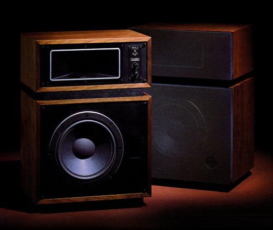
 The Model 14 was a one of a kind consumer loudspeaker from Altec Lansing. It incorporated their new Mantaray horn technology, along with a mid and high frequency equalization network. While the 14 appears to be just a smaller version of the older and larger Model 19, it’s substantially different in many ways. Altec also made a professional version, the 9842-8A/F, which had a more utilitarian cabinet design.
The Model 14 uses a 12″ Altec Lansing low frequency transducer part #34633 (Altec factory inventory #50-03-034633, cone kit RCA34633) to reproduce the range between 35 Hz and 1.5 kHz. It is sometimes mistakenly thought to have been manufactured by RCA due to the part number of the cone kit.
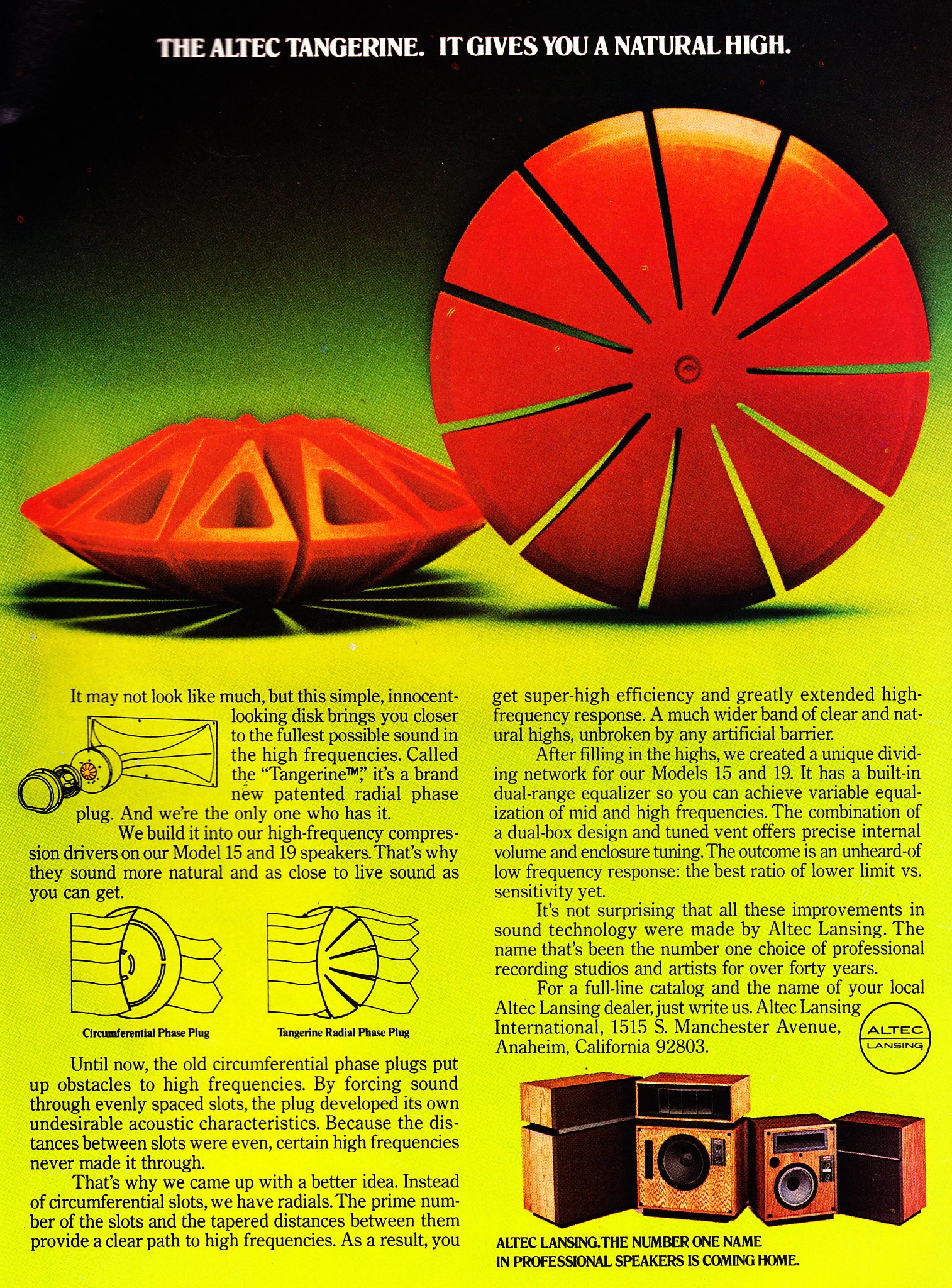
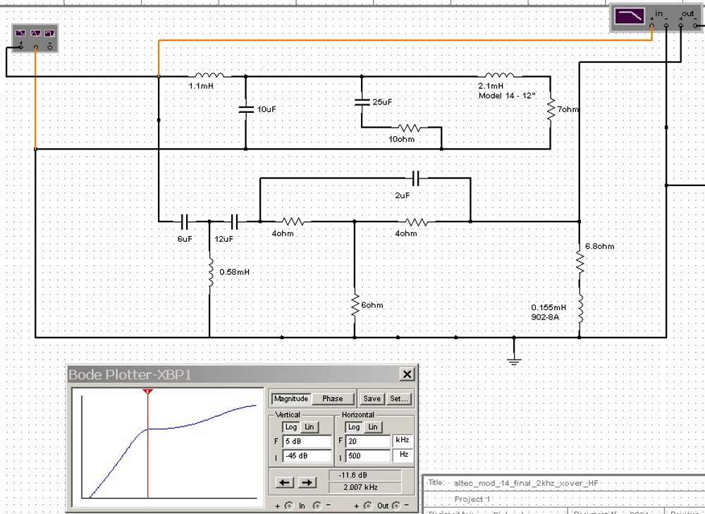
Mid and High frequencies between 1.5 kHz and 20 kHz are reproduced by the Altec Lansing 902-8B compression driver mounted to the newly designed MR931-12 Mantaray horn. The 902-8B utilizes Altec’s famous Tangerine phase plug for extended high frequency response. The Model 14 also incorporates a variable two band equalizer in its crossover circuit to correct mid and high frequency tonal balance based on listening preferences.
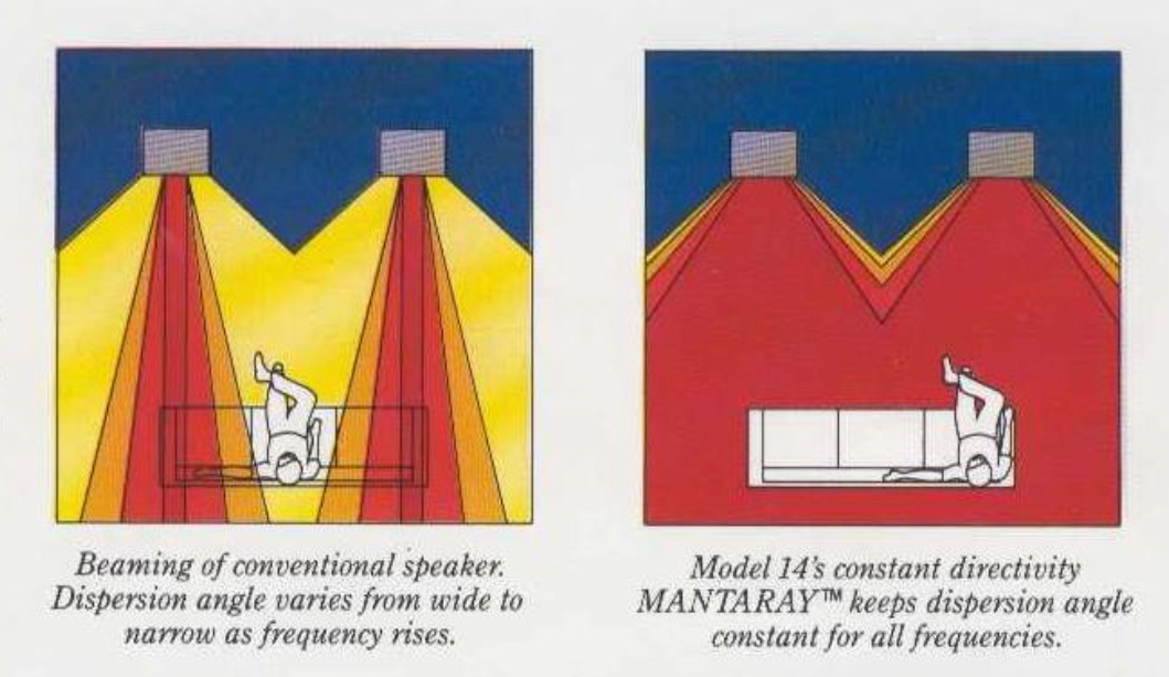 The Mantaray is a Constant Directivity (CD) design horn that keeps the dispersion angle constant for all frequencies, and reduces the beaming inherent in many loudspeakers. It was designed by Clifford A. Henrickson and Mark S. Ureda of Altec Lansing using the principles first established by Don Keele of Electro-Voice (later JBL).
The Mantaray separates desired vertical coverage patterns from horizontal, making it possible to design horns for a variety of coverage patterns. The Mantaray shape starts with a vertically oriented JBL-style diffraction horn leading into a conical waveguide (earliest designs) or a square or rectangular horn with four planar sides. For midrange beaming control, the outer mouth was expanded further with a short, flared flange in the Keele style, or with added planar sides of a greater flare angle. Low frequency efficiency was not as pronounced as the constant directivity design. Unlike previous designs, the apparent apex, the focal point of pattern dispersion, was not the same for every frequency, making for an ellipsoidal wavefront rather than spherical. Because of this, the Mantaray could only be arrayed satisfactorily in one plane. Its abrupt breaks in flare rate caused diffraction, reflection and distortion components. The same is also true of JBL’s 2344 Bi-Radial Constant Directivity design that was used in their 4425, 4430, and 4435 monitors. The JBL 4425 is very similar to the Altec Model 14.
Most popular Constant Directivity horns suffer from non-spherical wavefronts, limitations in arrayability, distortion at high sound pressure levels as well as reflections and distortions related to the transition from diffraction slot to secondary horn. They tend toward a narrowing of dispersion pattern at the higher frequencies whose wavelengths approach the width of the throat or the width of the diffraction slot.
Because the CD horn’s high frequencies are more spread out over its coverage pattern, they appear attenuated relative to other horns. The CD horn requires an equalization boost of approximately 6 dB per octave with a filter knee centered between 2 and 4 kHz (depending on horn design) in order to sound neutral and balanced. Most manufacturers of active electronic audio crossovers responded to this requirement by adding an optional CD EQ boost filter or high frequency shelf filter. Further refinements of the filtering process are available in DSP-based crossovers such as the dbx DriveRack PA2.
The limitations of these systems should not be over-blown. Both JBL’s 4425 and Altec’s Model 14 are excellent monitors by any standard, and will meet or exceed the expectations of most audiophiles, when properly setup.
 The crossover also introduced a sophisticated speaker protection circuit known as Automatic Power Control. Altec claimed this circuit added “absolutely zero distortion” and that it in no way limited frequency response. It’s purpose was to limit input power to 75 watts continuous RMS while allowing for dynamic peaks up to 200 watts. In the event of an overload it would automatically reduce power to the drivers by introducing a large resistor into the circuit via a relay. The listener was notified by a flashing red light on the crossover control panel. The system could also be tested by raising the input above 7 watts RMS and depressing the Overload Test button.
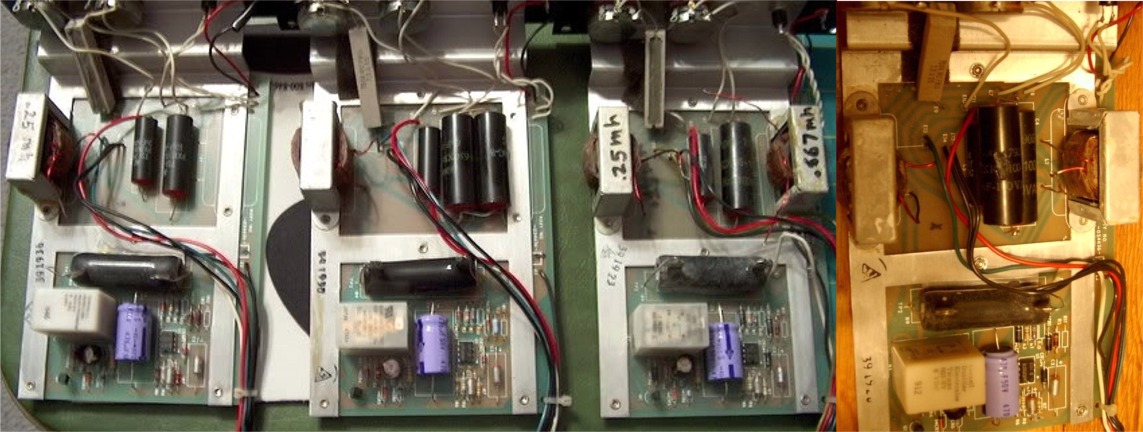
During its production run Altec issued four known revisions to the crossover circuit. Unfortunately, no one seems to know the order in which they were issued. All of the crossovers use a .25 mH inductor while two of them have an additional .667 mH inductor. The resistor leading from the board to the mid frequency equalizer control varies in value from 6 to 7.3 to 8 ohms, depending on the revision.
The front facing L-pads are not employed as such in the crossover’s design, instead they act as variable resistors in the equalization circuit mentioned above. The Mantaray CD horn requires this type of equalization to balance its high and mid frequency output. This can be bypassed when bi-amping with a DSP capable active crossover.
 Richard Christianson designed a new crossover for the Model 14 in the mid 2000s. He also took measurements of the #34633 low frequency transducer using the Woofer Tester II.
#34633 TS Parameters
Fs=22.4 Hz
Qes=.1569
Qms=6.8436
Qts=.1534
Zmax=261.65 ohms
Le=2.1394 mH
VAS=380 L (13.42 ft^3)
BL=15.8724 N/A
Sens=96.2 dB@1W/1M
Eff=2.63 %
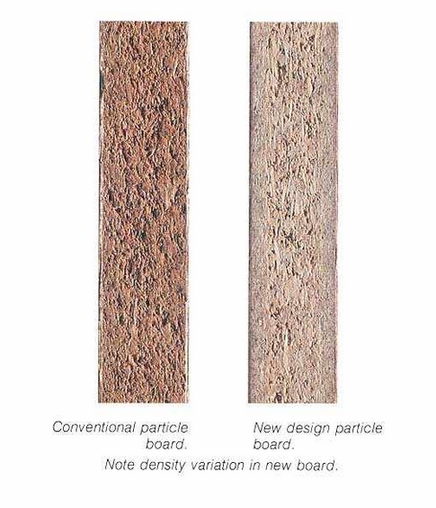
 The cabinet of the Model 14 is constructed out of a dual density particle board manufactured for Altec Lansing. The process causes the smallest wood particles to move to upper and lower surfaces, resulting in two dense layers separated by conventional particle board material. The exterior is finished in oiled walnut veneer.
 The cabinet is divided into four parts: horn enclosure, frame, woofer enclosure, and base. The frame is screwed to the bottom of the horn enclosure and two bolts on either side are passed through these into the woofer enclosure to make the complete cabinet. The base, which is essentially another frame, is screwed to the bottom of the woofer enclosure, and has four plastic furniture feet affixed to it. The cabinet is lined with R-6.7 fiberglass insulation.
The speaker terminals are located on the bottom of the cabinet and utilize spring loaded push pins that allow for a 16 AWG wire.
Altec Lansing Model 14 Specifications
Nominal Impedance: 8 ohms
Crossover Frequency: 1500 Hz
Enclosure Type: Vented
Sensitivity: 95dB (1W/1M 500 Hz – 3 kHz)
Frequency Response: 35 Hz – 20 kHz
Dynamic Range: 44 dB minimum crest factor above 70 dB SPL at 1 meter
Dispersion: 90° at -6 dB Horizontal, 40° at -6 dB Vertical (1 meter, 800 Hz – 8 kHz)
Continuous Power: 75 watts RMS
Recommended Power: 10 – 350 watts RMS
Continuous Acoustic Output: 114 dB at 1 meter
Dimensions: 30″H x 21″W x 16.5″D (with grill)
Weight: 77 lbs (34.9 Kg)
Click here to view the original Altec Lansing Model 14 sales brochure.
The information provided in this article is a compilation from various sources, including the Altec Lansing Forums, Wikipedia, Lansing Heritage and others.
